دوائر مزود القدرة
الفصل الأول
دوائر التقويم (دوائر مزود القدرة)
تتكون دائرة مزود القدرة من:
أ- المحول (Transformer)
ب- المقوم (Rectifier)
ج- دائرة التنعيم (Smoothing Circuit)
المحول (Transformer)
يوفر المحول الجهد المطلوب على الملف الثانوي.
المقوم (Rectifier)
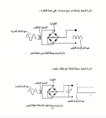
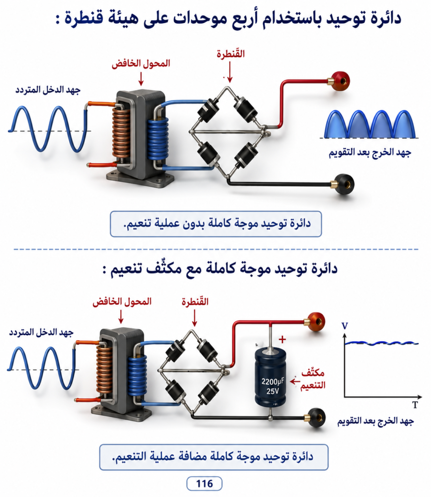
يقوم المقوم بتحويل التيار المتردد (AC) إلى تيار مستمر نابض (Pulsating DC).
في هذه التجربة يُستخدم مقوم جسر (Bridge Rectifier)، ويتكون من أربعة دايودات سيليكون، ويتم تقويم التيار طبقًا للحمل.
دائرة التنعيم (Smoothing Circuit)
أبسط أشكال دائرة التنعيم هي المكثف الإلكتروليتي (Electrolytic Capacitor).
يتم اختبار مكونات التجربة باستخدام جهاز الملتيميتر (Multimeter).
التجربة (1-1)
تنفيذ دائرة مقوم الجسر (Bridge Rectifier Circuit)
الهدف من التجربة
الحصول على جهد مستمر (DC) لتغذية الأجهزة الإلكترونية بالجهود اللازمة لتشغيلها.
نظرية التشغيل (Theory of Operation)
يقوم المحول بخفض جهد المصدر من 220 فولت متردد (220 VAC) إلى الجهد المطلوب للحمل (الجهاز المراد تشغيله).
يقوم مقوم الجسر بتحويل التيار المتردد إلى تيار مستمر نابض متغير الشدة ولكنه ثابت الاتجاه.
يعمل المكثف الإلكتروليتي على تنعيم التيار النابض الخارج من مقوم الجسر للحصول على تيار مستمر أكثر ثباتًا.
مكونات التجربة
محول قدرة 220VAC / 6VAC – 1A.
مقوم جسر (Bridge Rectifier) أو أربعة دايودات سيليكون.
مكثف إلكتروليتي لدائرة التنعيم.
خطوات التنفيذ
اختبار جميع المكونات باستخدام الملتيميتر.
تثبيت المكونات على لوحة الدائرة المطبوعة (PCB).
لحام أطراف المكونات على الوجه النحاسي باستخدام كاوية اللحام والقصدير.
التجربة
قياس جهد الخرج المستمر (DC Output Voltage) باستخدام الملتيميتر على وضع DC.
قياس جهد الخرج باستخدام راسم الذبذبات (Oscilloscope) بعد توصيل مقاومة حمل على طرفي الخرج، وملاحظة الإشارة عند:
طرفي الملف الثانوي للمحول.
طرفي خرج مقوم الجسر.
طرفي المكثف الإلكتروليتي.
تسجيل جميع النتائج.
دائرة التقويم باستخدام مقوم الجسر
العنصر الأساسي في دوائر التقويم الكامل للموجة (Full-Wave Rectifier) هو مقوم الجسر (Bridge Rectifier)، والذي يتكون من أربعة دايودات موصلة بطريقة معينة للحصول على تقويم كامل للموجة.
وتتوفر مقومات الجسر بأشكال مختلفة، وبقدرات مختلفة للتيار والجهد حسب التطبيق.
فيما يلي بعض أشكال مقومات الجسر وطريقة التعرف على أطرافها.
Chapter 1
Rectifier Circuits (Power Supply Circuits)
A Power Supply Circuit Consists of:
A. Transformer
B. Rectifier
C. Smoothing Circuit (Filter)
1. Transformer
The transformer provides the required voltage at the secondary winding by stepping the mains voltage up or down according to the circuit requirements.
2. Rectifier
The rectifier converts Alternating Current (AC) into Pulsating Direct Current (DC).
In this experiment, a Bridge Rectifier is used. It consists of four silicon diodes connected in a bridge configuration to produce full-wave rectification.
3. Smoothing Circuit
The simplest smoothing circuit consists of an electrolytic capacitor, which smooths the pulsating DC and produces a more stable DC output.
Experiment 1-1
Bridge Rectifier Circuit
Objective
To obtain a DC voltage suitable for supplying electronic circuits and devices with the required operating voltage.
Theory of Operation
The transformer reduces the mains voltage from 220 V AC to a lower AC voltage required by the load.
The bridge rectifier converts the low-voltage AC into pulsating DC.
The electrolytic capacitor filters the pulsating DC to produce a smoother and more constant DC voltage.
Components Required
1 × Power Transformer (220 VAC / 6 VAC, 1 A)
1 × Bridge Rectifier (or 4 × Silicon Diodes)
1 × Electrolytic Capacitor (Filter Capacitor)
Procedure
Test all components using a multimeter.
Place the components on the PCB (or breadboard).
Solder the components using a soldering iron and solder.
Measurements
Measure the DC output voltage using a multimeter.
Using an oscilloscope and a load resistor connected across the output terminals, observe the waveform at:
The transformer secondary terminals.
The bridge rectifier output terminals.
The electrolytic capacitor terminals.
Record all measured values and observed waveforms.
Bridge Rectifier Circuit
The essential component in a full-wave rectifier is the bridge rectifier. It consists of four diodes connected in a bridge configuration. Bridge rectifiers are available in different shapes and with different current and voltage ratings depending on the application.
Expected Waveforms
| Test Point | Waveform |
|---|---|
| Transformer Secondary | AC Sine Wave |
| Bridge Rectifier Output | Pulsating DC (Full-Wave Rectified) |
| Capacitor Output | Smoothed DC (Low Ripple) |

تمرين (2-1)
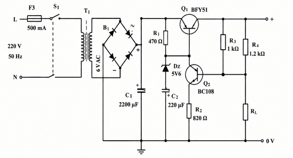
تنفيذ دائرة مثبت جهد بواسطة ترانزستور وثنائي زينر
الهدف من التمرين:
الحصول على جهد مستمر ثابت لتغذية الأجهزة الإلكترونية، وذلك من خلال:
الحصول على جهد عن طريق المحول على قيمة الجهد اللازمة لتغذية الحمل.
يقوم الترانزستور بتعويض تغير الجهد.
يقوم ثنائي الزينر بتثبيت جهد الخرج.
مكونات التمرين:
| م | المكون | المواصفات |
|---|---|---|
| 1 | محول | 220V / 6V AC – 1A |
| 2 | ترانزستور | BFY51 |
| 3 | ترانزستور | BC108 |
| 4 | دايود زينر | 5V6 |
| 5 | دايود توحيد | 1A |
| 6 | مقاومة ثابتة | 470Ω / 0.25W |
| 7 | مقاومة ثابتة | 820Ω / 0.25W |
| 8 | مقاومة ثابتة | 1kΩ / 0.25W |
| 9 | مقاومة ثابتة | 1.2kΩ / 0.25W |
خطوات العمل:
اختبار مكونات التمرين باستخدام الأوميتر وجهاز اختبار الترانزستور.
توزيع مكونات التمرين على لوحة البريكت (Breadboard).
لحام المكونات على الوجه النحاسي للوحة.
تجربة التمرين.
مكونات الدائرة الموضحة بالرسم:
F3 : فيوز 500mA
S1 : مفتاح تشغيل
T1 : محول 220V / 6V AC
B1 : قنطرة توحيد (Bridge Rectifier)
C1 : 2200µF
C2 : 220µF
Q1 : BFY51
Q2 : BC108
DZ : دايود زينر 5V6
R1 : 470Ω
R2 : 820Ω
R3 : 1kΩ
R4 : 1.2kΩ
RL : مقاومة الحمل
خرج الدائرة: (+) و (0V)
ملاحظة: تم تنسيق النص مع تصحيح الأخطاء الناتجة عن جودة الصورة، مع الحفاظ على المحتوى الأصلي كما هو.